| Guestbook |
Comments, questions? Visit to the
guestbook |
Overview
This model is from picture http://www.gbonline.com/~multiplx/wireless/pics/tincanant.jpg where is not found any theoretical principles but same construction is used in waveguide tube to coaxial adapters.
The antenna is constucted only of a cylindrical can and a N connector with centre tap lengthened. Just point the open end of the can to the ISP station and begin surfing. Oh, of cource there is needed some cable between the antenna and wlan card, see: Cabling details .
The can diameter is about 100 mm at 2.4 GHz band. It can be constructed e.g. from old time coffee tin can. Nowadays I haven't seen these in stores but maybe somewhere they can be found. The can dia have to be between 90 and 110 mm, side and bottom must be smooth and direct. If there are some burrs on the open end they have to smoothen e.g with hammer against base.
Dimensioning
Creech Lambda is replaced to L letter.
The length of the can is as is but best length maybe 3/4 Lg or more. The centre tap of the N connector is lengthened with 4 mm dia brass rod to Lo/4. Lo depends only on nominal frequency. Lo = 122 mm @ 2.45 GHz so Lo / 4 = 31 mm.
Lg depends on dia of the tube, here are some values:
| Inner dia of tube D / mm | Standing wave length Lg / mm | Lg / 4 |
|
|
|
|
| 95 | 186,7 | 47 |
| 100 | 175,7 | 44 |
| 105 | 167,6 | 42 |
| 110 | 161,5 | 40 |
|
***** NEW ***** The Calculator Engine
for dimensioning |
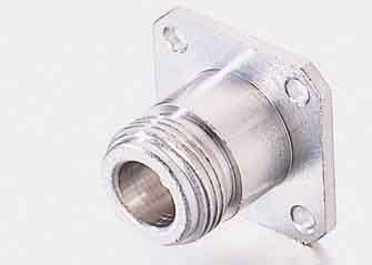
For a N-connector there is needed a 12 mm dia hole which distance is Lg / 4 from closed end. According the flange of the connector there are needed also four 3.5 mm holesi. The inner tap of the N connector is lengthened to Lo/4 or 31 mm with brass rod about 4 mm dia. Actually the length of the tap is not needed to be very accurate. I've proved several lengths from 25 to 40 mm and not found big differences although the impedance of the antenna is depending of the tap length. It's good idea to drill a 3mm hole axially to the end of the brass rod where the centre tap of the connector tightly goes. So the rod soldering becomes very firm.
N connector is fixed with four 3 mm screws so that bolts are pushed from inside of the tube and nuts screwed outside, so there becomes inside so less as possible extra taps, which can disturb the antenna function. The jointing of the connector and tube is sealed watertight with silicone mass. In the very lowest point of the tube there have be drilled a small hole for condensed water outlet.
The open end of the can needs a cap. The plastic material needed here must pass microwave oven test .
Antenna mounting to the antenna mast conduit can be made e.g. with some
kind of band round the cylinder to prevent the can flatten or dent.
Improved model
If the bottom of the can is not smooth a extra bottom can be added inside
the can. It can be made from tinned steel or aluminium which is cutted according
inside diameter of the can. How it is mounted inside the can there are countless
means. It is not neccessary be tight, microwaves are not passing through
narrow slots. Between the extra bottom and original bottom there becomes a
space with no need.
More effective version
The waveguide antenna can be equipped with a funnel which increases the
sensitivity of the antenna simply by collecting hf signal from larger area.
This adding increases the gain of the antenna by twice or 3 dB.
The right hand picture shows how the funnel is cutted from smooth tinned steel. Dotted lines are showing margins needed to joints. I made this antenna by air conditioning conduit with dia D = 100 mm where I added a bottom from tinned steel. The antenna dimensions are then: D = R1 = 100 mm, D2 = R2 = 170 mm, Lg/4 = 44 mm, Lo/4 = 31 mm, 3/4 Lg = 132 mm.
I used this antenna during about a week with good results until I got a even more effective antenna ready.
I haven't tested if it is possible to increase the outer dia D2 even more. The idea of the funnel is from the satellite receiver horn found in ARRL antenna book.
The open end of the funnel is closed with a microwave
proof plastic cap. Tighting of the joint of the N connector and
condenced water hole are similar as in the basic model.
Theory of the Waveguide Antenna
There are three different wavelengths in the waveguide tube. Here they are marked as Lo, Lc and Lg.
Lo is the wavelength of the hf signal in open air or
Lo/mm = 300 / (f/GHz).
Lc is the wavelength of the low cut frequency which depends on
tube dia only Lc = 1,706 x D
Lg is standing wavelength inside the tube, it is function of both
Lo and Lc
A waveguide which is closed on the other end acts similar as a short circuited coaxial cable. The coming hf signal reflects from ending point and there forms so called standing wave when incoming and reflecting signals in different places are either weakening or amplifiering each others:
If there is a measuring probe which is moving in axial direction inside
the tube there can be found some minimum and maximum points in certain intervals.
At the closed end the signal is zero and so will be in halfwave intervals.
The first maximum point is quarterwavelength from the closed end. This will
be the best place to outlet signal to coaxial line. You can notice that maximum
area is quite flat. So the place of the outlet must not be very accurate.
It is important to notice that the standing wavelength Lg is not the same as wavelength Lo counted from hf signal. Large tubes are near as open air where Lg and Lo are almost same but when tube diameter becomes smaller the Lg increases effective until there becomes a point when Lg becomes infinite. It corresponds the diameter when hf signal doesn't come to the tube at all. So the waveguide tube acts as a high pass filter which limit wavelength Lc = 1.706 x D. Lo can be calculated from nominal frequency: Lo/mm = 300/(f/GHz). Inverse values of Lo, Lc and Lg forms a right angled triangle where becomes the equation of Pythagoras:
(1/Lo)2 = (1/Lc)2 + (1/Lg) 2
which can be solved
Lg = 1 / SQR((1/Lo)2 - (1/Lc)2)
In the antenna the N connector is situated in maximum point or length
of Lg/4 from the closed end. Total length of the tube is selected so that
the next maximum place hits on the open end of the tube or 3/4xLg from the
closed end. The latter is only supposed by my own and found be not the worst
decision.
A Fiction
 I cast here a model I have thinked. Why not use waveguide tube instead
of antenna cable too. The tube shall be so height that the lower end reaches
to near the wlan card of the computer. The tube shall be made of 100mm air
conditioning conduit with a curve and a funnel. The construction is very
resistance against lightnings too I believe. There it will be like a horn
of a steamboat. If someone will build this please feedback results.
I cast here a model I have thinked. Why not use waveguide tube instead
of antenna cable too. The tube shall be so height that the lower end reaches
to near the wlan card of the computer. The tube shall be made of 100mm air
conditioning conduit with a curve and a funnel. The construction is very
resistance against lightnings too I believe. There it will be like a horn
of a steamboat. If someone will build this please feedback results.
Sources:
ARRL Antenna Book
ARRL UHF/Microwave Experimenter's Manual ISBN: 0-87259-312-6
17. July 2001
29. September 2002 The Calculator added
Martti Palomaki
Ilmajoki
![]()